Laser Line in RViZ is shifting while moving the differential drive robot

Hi all,
I am working on my own URDF in ROS2.

After launching robot in Gazebo and Rviz2, I found that laser line position in rviz is not matching with the wall position of gazebo environment. Laser line in rviz is also shifting while I am rotating the robot.

tf_tree

Please support.

Hi @Dharankumar ,

You either have a bad odometry or your diff_drive plugin configuration is incorrect.

Regards,
Girish

Hi,

This is the configuration for diff_drive. Please check it.

Hi @Dharankumar ,

You need to check your kinematics values and limits values that you have designed for your robot and use the proper values.
Your plugin definition looks fine to me when looking at it. But I would not know if your robot specifications are correct.
You need to check and debug that to know what is the issue.
If your values are precise and correct, then you might have an issue with your simulation odometry.
You might have to implement a filter for odometry to get fine tuned odometry values.

Regards,
Girish

Hi,

Thank you so much @Girishkumar for your suggestion. As per you suggestion, I checked dimension and position of all links and I found all are fine.

In the last video, kinematics was like Lidar link was shifted in x_axis and z_axis w.r.t base link and was getting this laser shifting problem.

Now I kept lidar link on top of base link, that mean lidar link is shifted only in z_axis. In this case I am getting Lase line position correct and also it is not shifting while rotating the robot in simulation(rviz).

Here you can check the video.

Can you please explain what could be the possible reason for this problem?

Hi @Dharankumar ,

I looked at your video closely for a few times. I don’t see any issues.
What exactly is not happening as expected? I need more info on this new video situation.

Regards,
Girish

Hi,

You can compare with last video and recent video. If I put Lidar on top of base_link then only laser Red line coming proper or else it is coming wrong.

Hi,

I am simulating my own urdf in gazebo and visualizing in rviz. The problem I am facing here is about laser line position in rviz and and actual position of the object or wall in gazebo.

Case1 and Case2 for own robot simulation and Case3 for turtlebot3_waffle simulation.
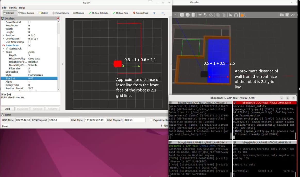
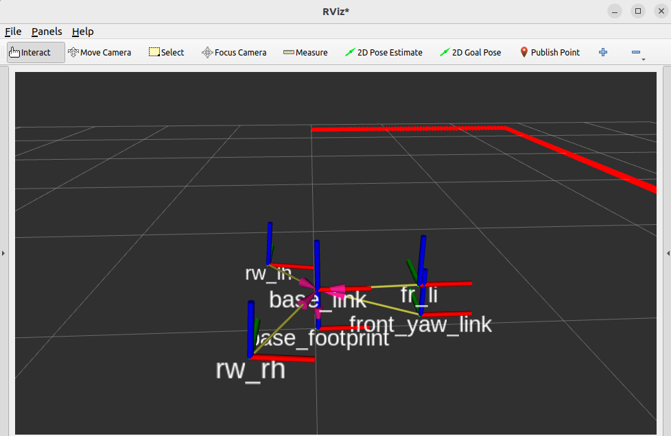
Case1:
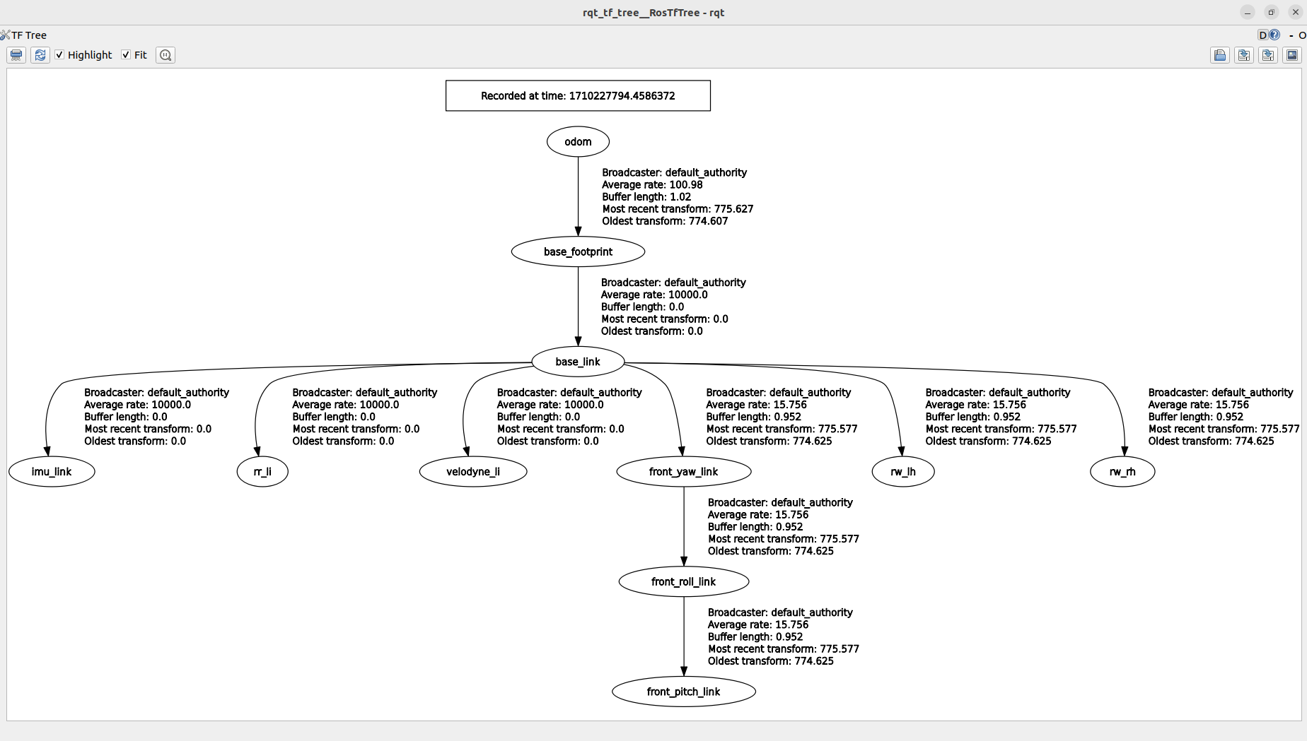
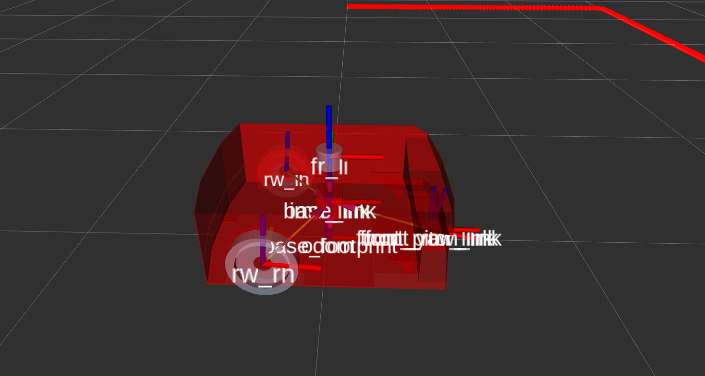
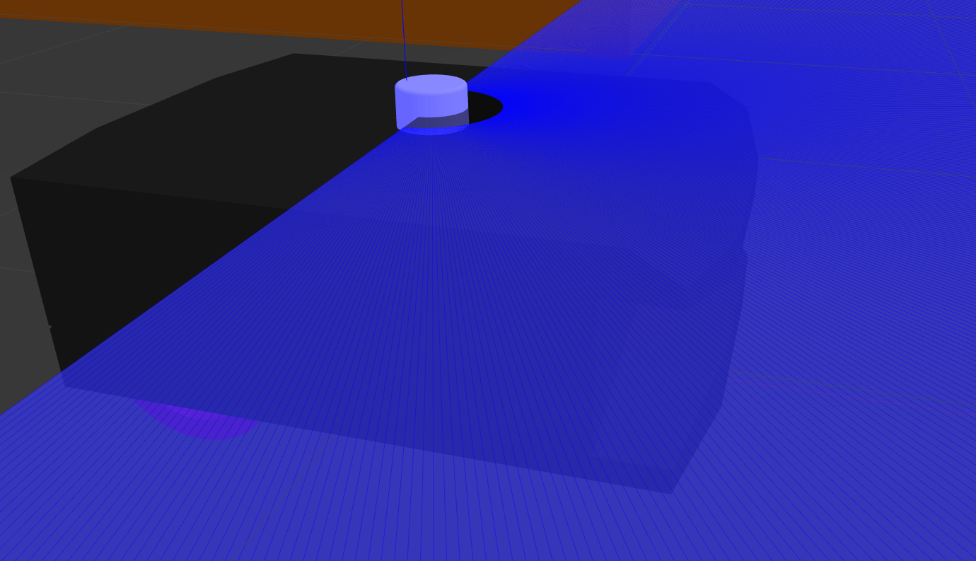
Here I put Lidar_joint origin at x=0.383, y=0, z=0.1 , r=0, p=0, y=0 and here parent link is base_link and child link is Lidar_link. In this case actual wall in gazebo is situated, approx 2.5 grid line away from the front face of the robot but laser red line I am getting in rviz is about 2.1 grid line away from the front face of the robot. You can see in the image and video attached below

In this case If I rotate the robot in gazebo, in rviz laser red line shifts its position.
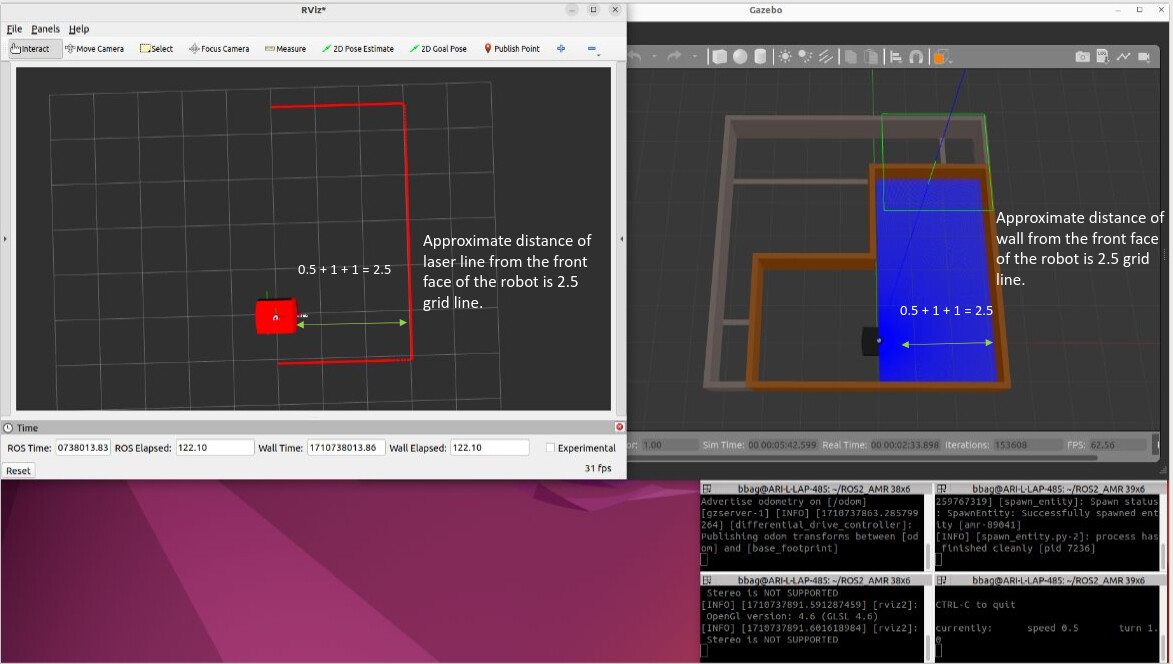
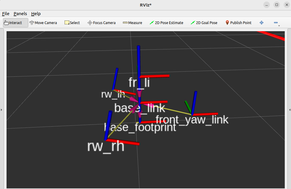
Case2:

Here I put Lidar_joint origin at x=0, y=0, z=0.2 , r=0, p=0, y=0 and here parent link is base_link and child link is Lidar_link(same as Case1). In this case actual wall in gazebo is situated, approx 2.5 grid line away from the front face of the robot and laser red line I am getting in rviz is also 2.5 grid line away from the front face of the robot. You can see in the image and video attached below

In this case If I rotate the robot in gazebo, in rviz laser red line stays in same position.

Case3:

When I simulated turtlebot3_waffle in the same world, I did not find laser position error and shifting in rviz like Case1. Another thing I saw that turtlebot use .sdf file for gazebo simulation and .urdf fie for visualizing in rviz.

Conclusion:

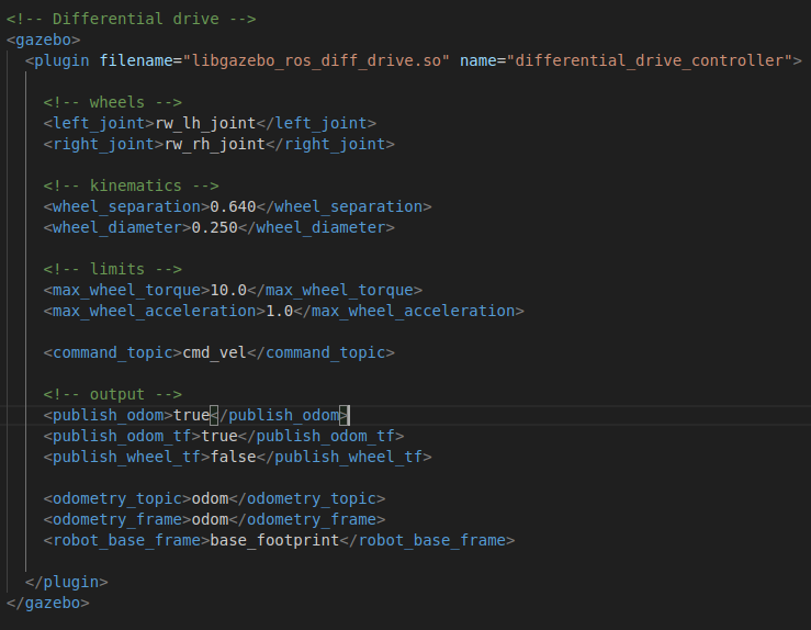
Case2 and Case3 is giving expected result. I want to know that, while simulating a robot using urdf format is it required to keep lidar exactly on top of the base_link or reference_link for getting correct laser line in rviz. I checked with other urdf and construct video also, I found that when they are putting lidar on top of reference_link then only they are getting correct laser line or else if they shift the lidar in x-axis w.r.t reference_link then they are getting wrong laser line in rviz.

Should I use both .sdf and .urdf for correct output?

Please check the problem, I got stuck for a while.

Hi @Dharankumar ,

Could you please share the robot model and TF names view alone without the laser scan lines?

Just the robot on an isometric view on Rviz with RobotModel (with 0.5 alpha value) and TF (with names enabled and 0.5 marker scale)?

That would be more helpful to understand your situation.

Regards,
Girish

Hi,

Can you please check with TF? Here is the TF of the robot for two cases.

base_footprint is the dummy parent link of base_link.
body of robot is attached with base_link.
rw_lh → rear left wheel
rw_rh → rear right wheel
front_yaw_link → front wheel
fr_li → front lidar

Case1:

Case2:

Hi @Dharankumar ,

Could you also please post the robot model so I know how you have put the lidar (alignment and placement).

Also, how are you generating the scans for the Lidar? As vertical or horizontal?
I think in case 1, where you have the Lidar in the front of the robot, you should have vertical rays set. But in case 2, where you put the Lidar on top of the robot, you should have horizontal rays set.

Regards,
Girish

HI,

Case1:

Case2:

In both cases laser ray is horizontal.

Hi @Dharankumar ,

I think what you have done in Case 1 and Case 2 is correct.
My assumption for why the laser lines are moving in your case 1 on rviz, is that you have set the Fixed Frame to something else other than base_link or base_footprint. Probably you have set it to the laser frame or something else.
The reason is that, when you put the laser on top of base_link in case 2, you don’t see the laser lines move, but in case 1, where the laser is not right on top of base_link, you see the changes.
So, try setting the Fixed Frame to base_link or base_footprint or odom or map. That should work.

Regards,
Girish

This topic was automatically closed 5 days after the last reply. New replies are no longer allowed.